Think Diagnostic Procedure
DIAGNOSTIC PROCEDURE FOR TH!NK NEIGHBOR TSB 05-4-12 ON-BOARD BATTERY CHARGER
THINK:
2002 Th!nk Neighbor
|
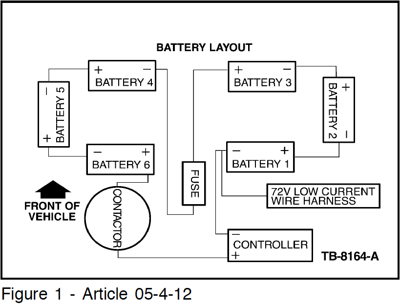
Issue:Some TH!NK Neighbor electric vehicles may display a low range, no start, or no charging condition. This may be due to the on-board battery charger either overcharging, undercharging, or not charging at all. These conditions may cause associated damage to the battery pack, resulting in battery pack replacement. The following is an optional service procedure to supplement the Workshop Manual procedure to properly diagnose the function of the on-board battery charger. Service Procedure: WARNING: THIS VEHICLE CONTAINS HIGH-VOLTAGE COMPONENTS AND WIRING. THE BATERY PACK ASSEMBLY CAN DELIVER IN EXCESS OF 72 VOLTS OF DC POWER. HIGH-VOLTAGE INSULATED SAFETY GLOVES AND FACE SHIELF MUST BE WORN WHEN PERFORMING THIS TSB. FAILURE TO FOLLOW THIS WARNING, OR IMPROPER HANDLING OF THE BATTERY PACK MAY RESULT IN SEVER PERSONAL INJURY OR DEATH. ONLY AUTHORIZED PERSONNEL TRAINED TO WORK WITH HIGH-VOLTAGE AND BATTERY PACK COMPONENTS ARE PERMITTED TO HANDLE THE BATTERIES. CAUTION: BEFORE WORKING ON THE BATTERY PACK, THE SERVICE DISCONNECT SWITCH (SDS) MUST BE TURNED OFF. THE SDS SHOULD REMAIN OFF FOR THE DURATION OF THIS PROCEDURE. NOTE: FORD MOTOR COMPANY MAY REQUEST THE RETURN OF THE CAUSAL COMPONENT(S) LEADING TO BATTERY PACK REPLACEMENT WHEN BATTERIES ARE REPLACED UNDER WARRANTY, ALL RELATED CAUSAL COMPONENTS MUST BE HELD FOR 30 DAYS FROM THE CLAIM SUBMISSION DATE. BE SURE TO INCLUDE BATTER PACK AND INDIVIDUAL BATTERY VOLTAGES, ALONG WITH BATTERY CHARGER OUTPUT VOLTAGE, IN COMMENTS AREA OF THE REPAIR ORDER. 1. Remove the front seat stanchion and check battery pack voltage by placing a DVOM positive (+) probe onto the positive terminal of battery #6, and the DVOM negative (-) probe onto the negative terminal of battery #1 (Figure 1) a. If the voltage reading is above 20V, proceed to step 7. b. If voltage is below 20V, proceed to step 2.
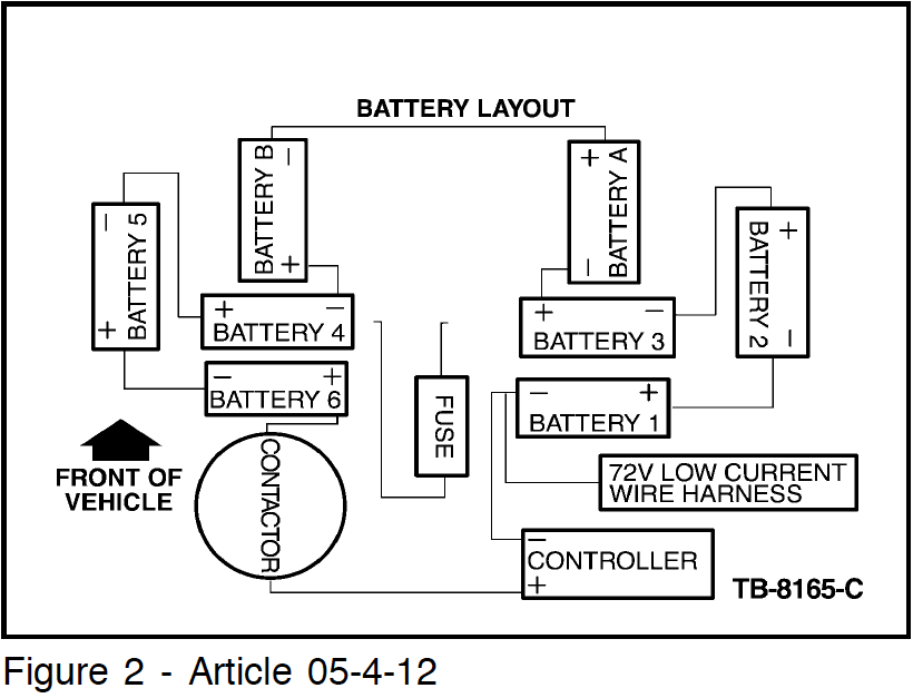
2. Obtain twp (2) known good batteries (Part # 10655). Check the batteries to be sure they produce at least 11v each or 22v combined. These batteries will be referred to as batteries A and B for the remainder of this TSB. 3. CRITICAL, USING HIGH VOLTAGE GLOVES, disconnect the following battery cables: battery #3 (+), and battery #4 (-) 4. Connect the (+) terminal of battery A to the (-) terminal of battery B, (an extra TH!NK Neighbor battery cable or jumper cable may be used to make the connection). |
5. Connect the (+) terminal of battery B to the (-) terminal of the battery pack # 4 battery (Figure 2). Connect the (-) terminal of battery A to the (+) terminal of the battery pack #3 battery.
6. Place the DVOM (+) probe onto the (+) terminal of battery #6 and the (-) probe onto the (-) terminal of battery #1. 7. Using the customer's GFCI cord: a. Plug the cord into the 110V wall outlet. b. Turn-off the GFCI cord breaker by pressing the (TEST) button on the GFCI block. c. Plug in the GFCI receptacle end into the vehicle charge inlet. d. Turn-on Power to the charger by pressing the (RESET) button on the GFCI cord breaker. 8. Within 3 minutes of plugging the charger in, the voltage reading on the DVOM should start to rise. a. If the voltage rises, this means tha the charger is working. However, continue to monitor the DVOM until the voltage hits its highest point (peaks). (1) If the voltage rises above 90V, the charger is overcharging and should be replaced. (2) If the voltage rises but never reaches 75V or above, the charger is under charging and should be replaced. b. If the voltage does not rise after 5 minutes, the charging system is not charging. (1) Check the function of charging system components such as the GFCI cord, the charger, 30-amp fuse and the charge circuit. Make repairs as necessary and retest. If no faults are found with the system components, replace the charger. 9. After completing the charger diagnostics, shut-off the power through the GFCI charge cord by pressing the (TEST) button on the GFCI breaker on the GFCI cord, and remove the cord from the vehicle plug inlet. 10. CRITICAL, USING HIGH VOLTAGE GLOVES, disconnect battery cables from the A and B jumper batteries to the vehicle batteries at battery #3 (+), and the battery #4(-). Reconnect the vehicle pack battery cables. |


